Arty MPW tester
The Arty MPW tester is simple expansion board compatible with Digilent Arty A7 development kit. This board connects IO signals from the Xilinx Artix FPGA located on the Arty board to an open hardware Caravel breakout board. The Caravel breakout board allows testing ASIC designs prepared for Multi Project Wafer (MPW) shuttles and fabricated with one of the available open Process Design Kits (PDKs).
The hardware is open and can be found on GitHub: https://github.com/antmicro/arty-mpw-tester/
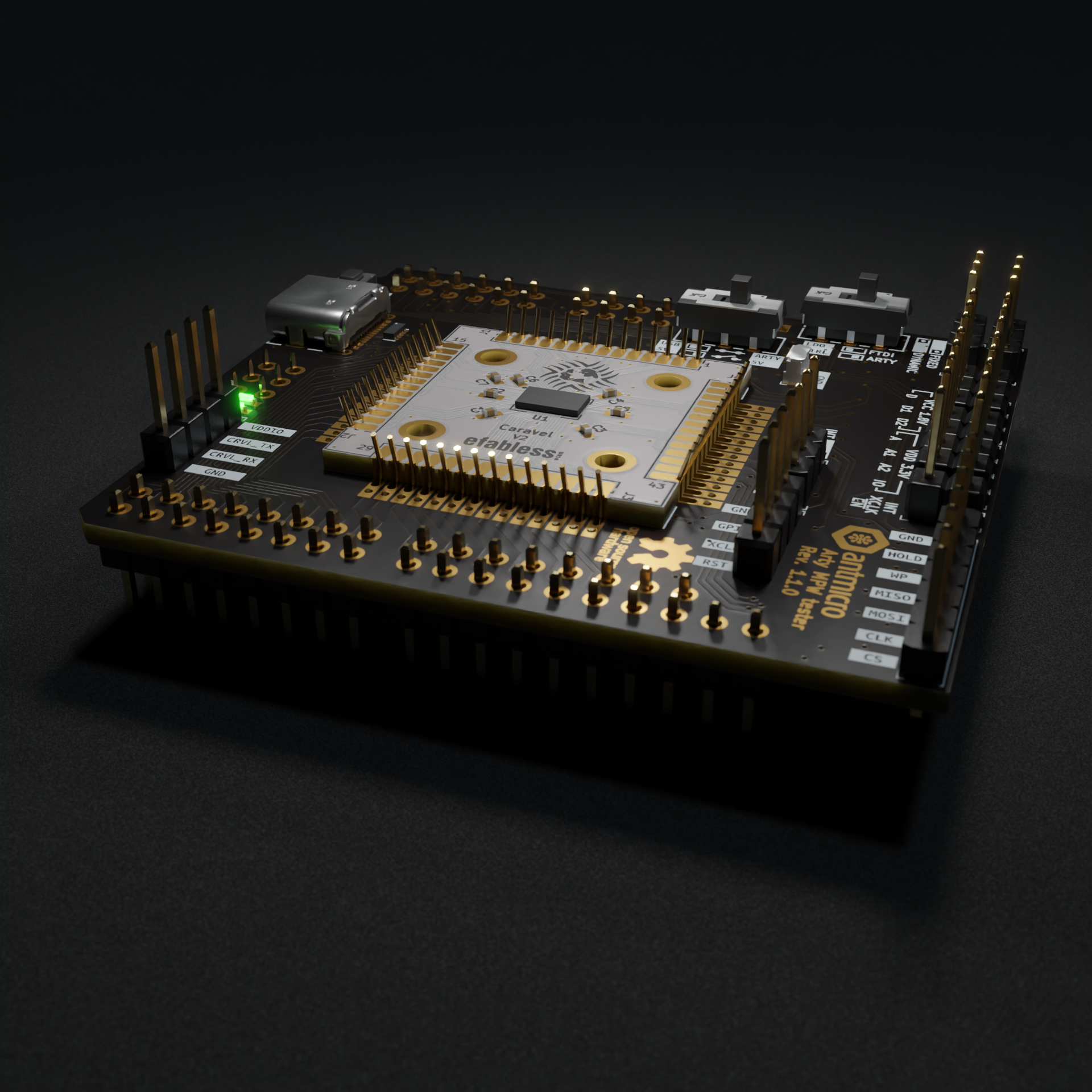
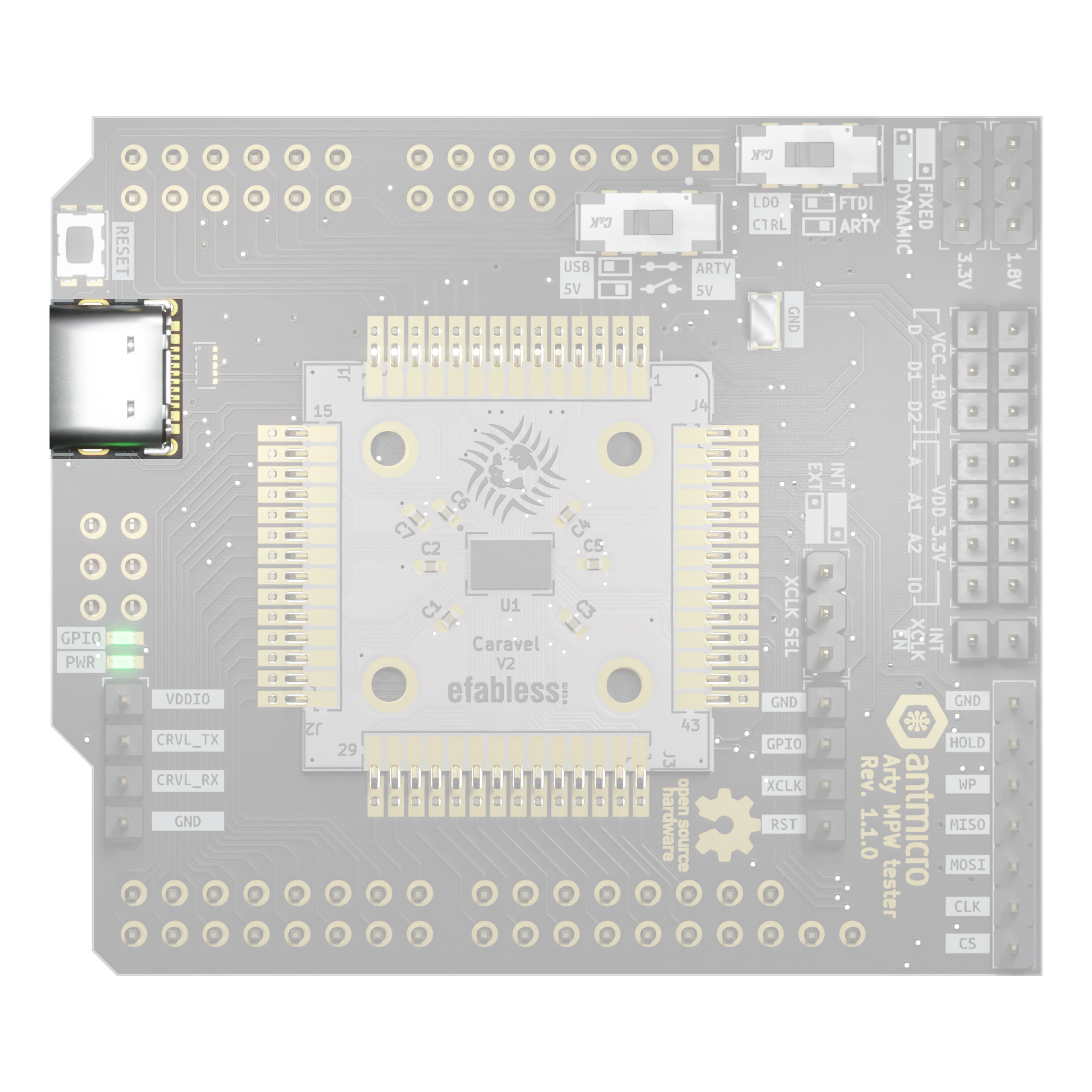
Diagram below represents overview of whole board:

The following instructions explain how to set up the board for MPW testing.
Arty MPW tester configuration
Arty MPW tester was designed to give user flexibility in configuration of the tester.
User can independently configure:
Power
FTDI with 2 SPI’s and UART
Source for Caravel-breakout XCLK (internal oscillator / Arty IO42 pin)
Internal XCLK source (enable/disable)
Power
The Arty MPW tester can be supplied either from Arty or USB connector.
Note
Both power sources are always connected to the dual LDO via protection diodes.
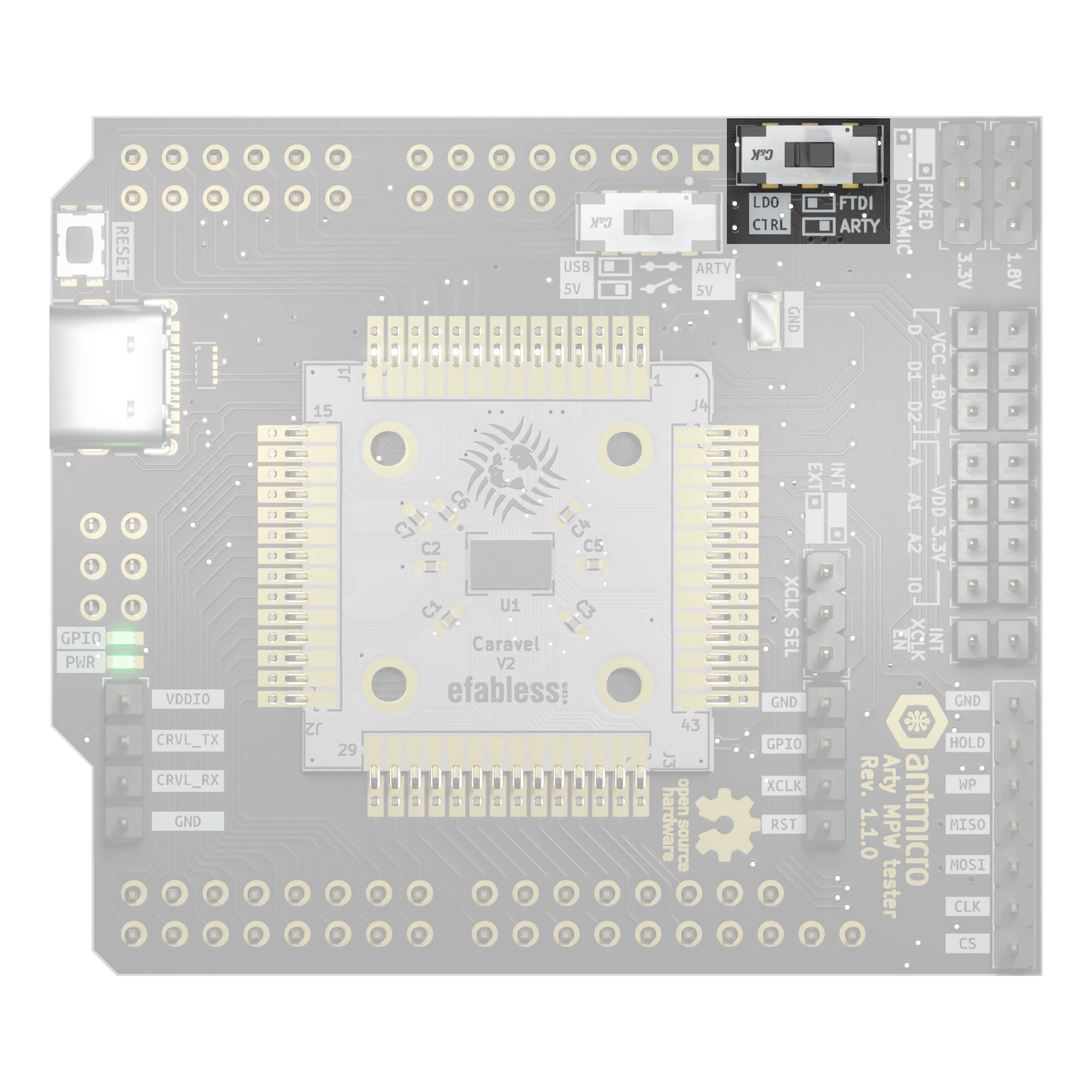
Fixed/dynamic LDO selection
The Arty MPW tester features dual LDO supplying 1.8V and 3.3V rails. Each rail can be set to either:
FIXED- supplying fixed 1.8V or 3.3V depending on railDYNAMIC- allowing user set LDO voltage using I2C digipot
I2C digipot (MCP4661-103E/ML) is used to dynamically adjust 1.8V and 3.3V rail voltages.
Placing jumper on position FIXED on either 1.8V and/or 3.3V rail bypasses digipot and forces LDO into fixed voltage regulation on given rail.

Rail EN control
Both 3.3V and 1.8V rails can be enabled separately using EN1 and EN2 pins of the LDO.
LDO CTRL switch can be set in two positions:
ARTY- connects the Arty A7 board to theEN1/2pins of the dual LDOFTDI- connects the FTDI to theEN1/2pins of the dual LDO
Individual rail connections
Each of the power rails routed on Caravel breakout is exposed on 1x2 2.54mm pin header allowing for selecting which rails are enabled.
Using this header it is also possible to manually inject voltage into separate rails.

Caravel rails measurement
All 7 power rails of Caravel breakout are also connected to power monitors which allow measuring voltage and current used by the board. Measurement is based on 2 4-channel PAC1954T chips. User can communicate with chips with I2C interface and Arty board as controller. SMBus addresses of chips are 0b0011111 and 0b0010000.
Arty / USB rail connection
Warning
This feature should be used only to supply Arty from Arty MPW tester.
Switch allowing connection of the 5V USB and 5V Arty rails can be set in two positions:
OPEN- USB 5V and Arty 5V rails are separatedCLOSED- USB 5V and Arty 5V rails are connected, allowing to supply Arty from Arty MPW tester

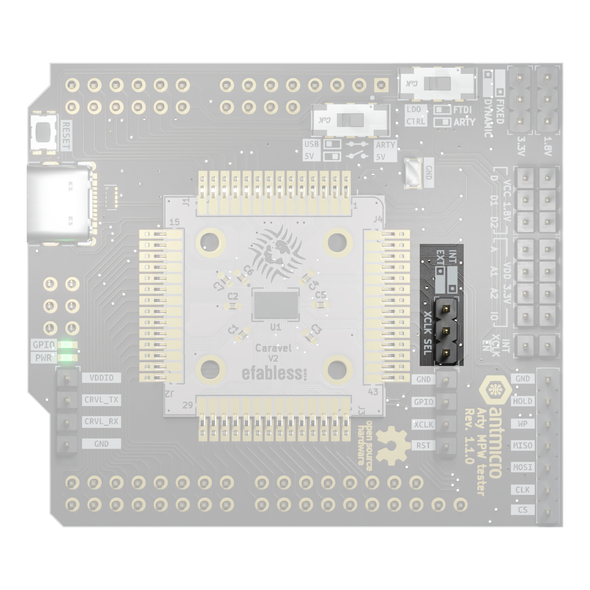
XCLK
Clock supplied to the Caravel breakout can be sourced in two ways.
Using XCLK SEL header user can switch between:
INT- sourcing XCLK from onboard oscillatorEXT- sourcing XCLK from Arty IO42 pin
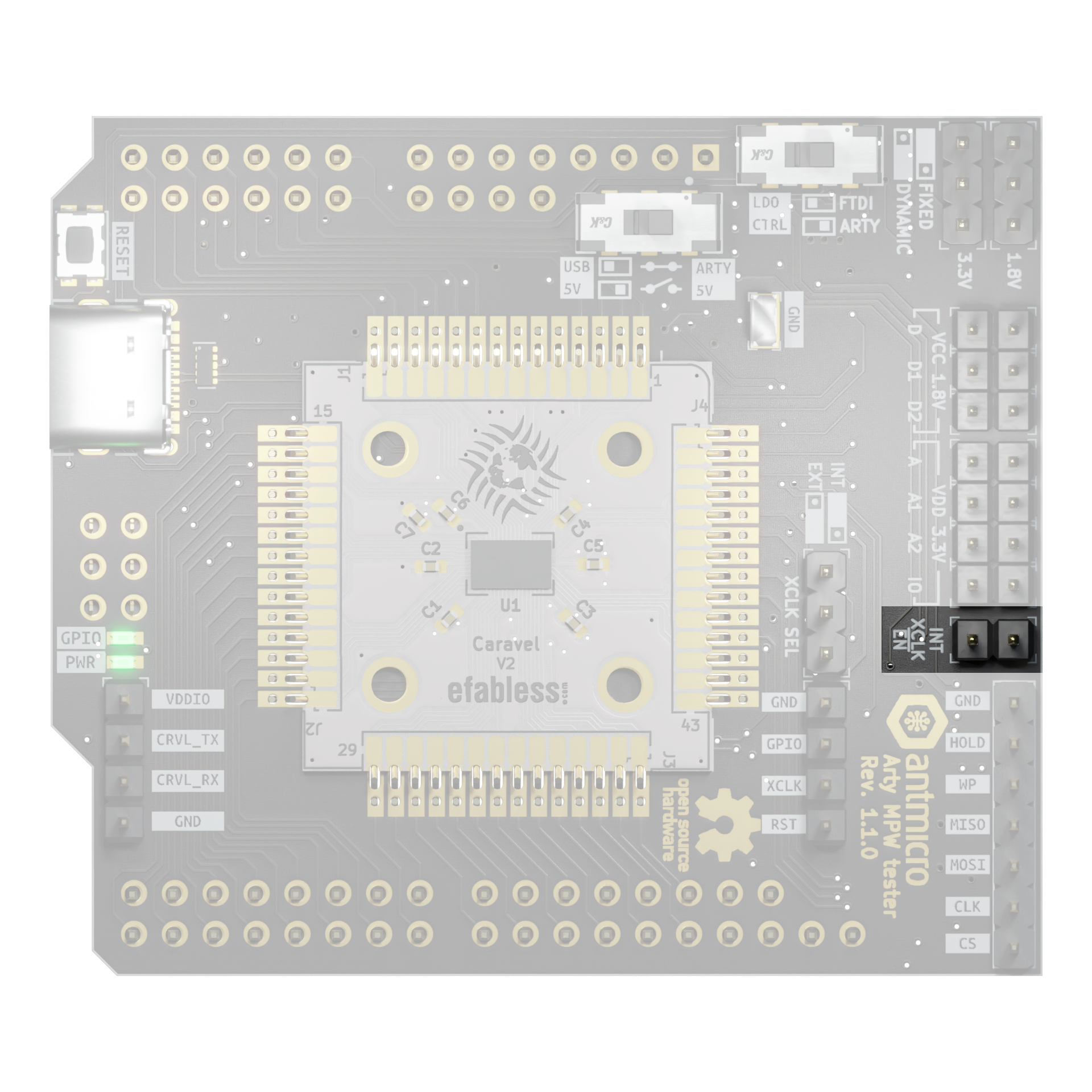
When XCLK SEL is set to INT user can enable and disable onboard oscillator using INT XCLK EN header:
FTDI
Tester board is equipped in 4-channel FTDI module (FT4232H). User can communicate with it by built-in USB-C connector, which can also power up whole board.
FTDI chip has channels A and C connected to Caravel board with SPI and UART protocols. Channel B communicates with on-board flash memory chip via SPI protocol.
Chip has also 3 additional GPIO pins with functions of reset FTDI and 2 enables of dynamic LDO (1V8 and 3V3).
Default configuration
Before plugging USB to Arty MPW Tester or Arty board make sure that configuration jumpers and switches are set correctly.
Default configuration for the Arty MPW tester is as follows:
Setting |
Slide switch |
Jumper |
|---|---|---|
1.8V LDO |
Fixed |
|
3.3V LDO |
Fixed |
|
LDO CTRL |
ARTY |
|
VCC 1.8V D |
YES |
|
VCC 1.8V D1 |
YES |
|
VCC 1.8V D2 |
YES |
|
VDD 3.3V A |
YES |
|
VDD 3.3V A1 |
YES |
|
VDD 3.3V A2 |
YES |
|
VDD 3.3V IO |
YES |
|
IN XCLK EN |
NO |
|
XCLK SEL |
EXT |
|
Arty 5V - USB 5V |
OPEN |
Picture below presents default configuration for slide switches and jumpers

Pinouts
Caravel - Arty interface
Caravel breakout |
FPGA Pin |
ChipKit pin |
Dedicated function |
|---|---|---|---|
IO00 |
R18 |
IO39 |
|
IO01 |
P17 |
IO13 |
SPI MISO |
IO02 |
T18 |
IO38 |
SPI MOSI |
IO03 |
R17 |
IO12 |
SPI CS |
IO04 |
U17 |
IO37 |
SPI SCK |
IO05 |
U18 |
IO11 |
Caravel RX |
IO06 |
N14 |
IO36 |
Caravel TX |
IO07 |
V17 |
IO10 |
|
IO08 |
N16 |
IO35 |
|
IO09 |
M16 |
IO09 |
|
IO10 |
R16 |
IO34 |
|
IO11 |
N15 |
IO08 |
|
IO12 |
P15 |
IO33 |
|
IO13 |
T16 |
IO07 |
|
IO14 |
R15 |
IO32 |
|
IO15 |
T15 |
IO06 |
|
IO16 |
R13 |
IO31 |
|
IO17 |
T14 |
IO05 |
|
IO18 |
R11 |
IO30 |
|
IO19 |
R12 |
IO04 |
|
IO20 |
R10 |
IO29 |
|
IO21 |
T11 |
IO03 |
|
IO22 |
M13 |
IO28 |
|
IO23 |
P14 |
IO02 |
|
IO24 |
V16 |
IO27 |
|
IO25 |
U16 |
IO01 |
|
IO26 |
U11 |
IO26 |
|
IO27 |
V15 |
IO00 |
|
IO28 |
A3 |
A11 |
|
IO29 |
D5 |
A5 |
|
IO30 |
A4 |
A10 |
|
IO31 |
D7 |
A4 |
|
IO32 |
E5 |
A9 |
|
IO33 |
E7 |
A3 |
|
IO34 |
E6 |
A8 |
|
IO35 |
C7 |
A2 |
|
IO36 |
B6 |
A7 |
|
IO37 |
D8 |
A1 |
|
GPIO |
M17 |
IO42 |
|
FLASH SO |
G1 |
MISO |
|
FLASH SCK |
F1 |
SCK |
|
FLASH SI |
H1 |
MOSI |
|
FLASH CS |
C1 |
SS |
Caravel - FTDI interface
Caravel breakout |
FTDI |
|---|---|
IO01 |
ADBUS2 |
IO02 |
ADBUS1 |
IO03 |
ADBUS3 |
IO04 |
ADBUS0 |
IO05 |
CDBUS0 |
IO06 |
CDBUS1 |
FTDI - SPI Flash interface
| SCK | BDBUS0 | | SO | BDBUS1 | | SI | BDBUS2 | | CS | BDBUS3 |
Control pins
Function |
FTDI |
FPGA Pin |
ChipKit pin |
|---|---|---|---|
LDO EN1 (3.3V) |
BDBUS5 |
F5 |
A0 |
LDO EN2 (1.8V) |
BDBUS6 |
B7 |
A6 |
Caravel RESET |
BDBUS4 |
N17 |
IO41 |
XLCK |
- |
P18 |
IO40 |
DIGIPOT SCL |
- |
L18 |
SCL |
DIGIPOT SDA |
- |
M18 |
SDA |
MPRJ UART header
|
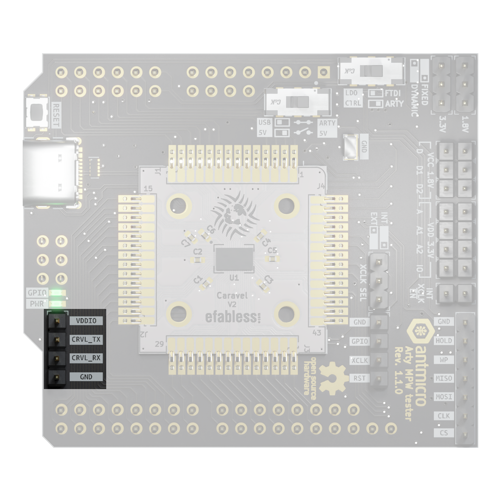
|
SPI flash and Caravel MGMT headers
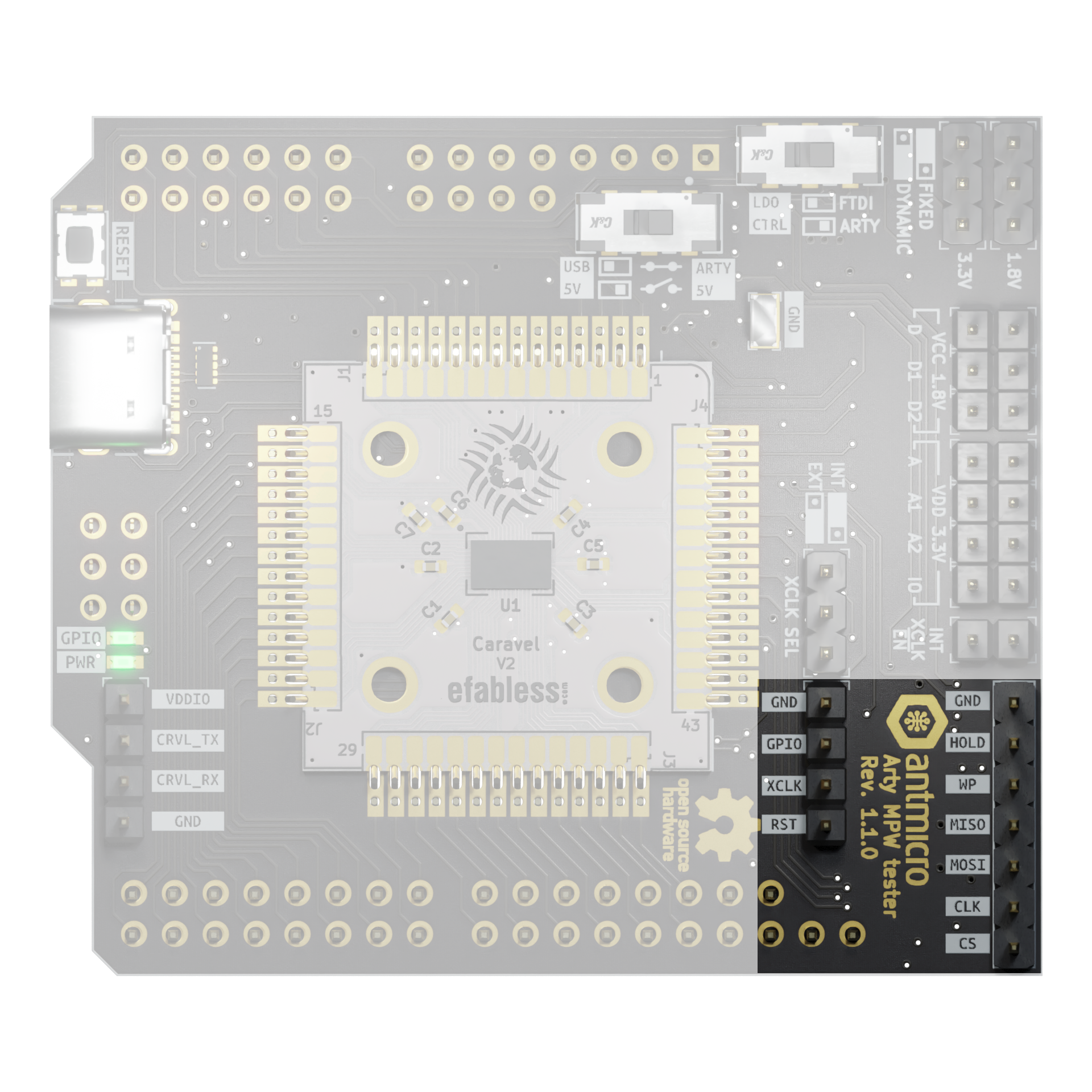
|
|
|